Introduction to Parallel Access Shift Registers
What are the Parallel Access Shift Registers? In computer systems, it is frequently essential to transport n-bit data items from one location to another. This can be accomplished by transferring all bits at the same time over n distinct cables, in which case the transfer is referred to as being completed in parallel. The transfer of all bits across a single wire, on the other hand, can be accomplished by transferring each bit one bit at a time over a period of n consecutive clock cycles.
Serial transfer is the term used to describe this technique. To transport an n-bit data item serially, we can make use of a shift register, which can be loaded with all n bits in parallel and then transferred serially (in one clock cycle). The contents of the register can then be moved out for serial transfer during the next n clock cycles, if the register is still active. It is also necessary to perform the inverse operation. If bits are received serially, the contents of the register can be read in parallel as an n-bit item after n clock cycles if the bits are received serially.
An example of a four-bit shift register that allows for parallel access is shown in figure below To avoid the use of the standard shift register connection, the D input of each flip-flop is connected to two separate sources instead of one. One of these sources is the flip-flop that came before it, which is required for the shift register action.
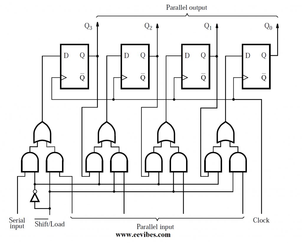
Other sources include an external input that corresponds to the bit that will be loaded into the flip-flop as part of the parallel-load operation and an internal input that will be used for other purposes. The mode of operation is selected by the use of the control signal Shift/Load. If the ratio of Shift/Load is zero, the circuit behaves as a shift register. If Shift/Load = 1, the parallel input data is loaded into the register. Otherwise, it is not loaded. This means that in both instances, the action takes place on the positive edge of the clock.
Because shift registers are frequently used to store binary integers, we have opted to designate the flip-flop outputs in above figure as Q3,…,Q0. In parallel with this, the outputs of all flip-flops can be observed to gain access to the contents of the register. The flip-flops can also be accessed serially by watching the values of Q0 over a period of consecutive clock cycles while the contents of the flip-flops are shifting. It is referred to as a series-to-parallel converter when the data may be fed in series and then accessed in parallel on the same circuit. A parallel-to-series converter, on the other hand, is the polar opposite of this form of circuit.
Also read here
- how to draw state diagram of sequential circuit?
- What is the magnitude comparator circuit? Design a 3 bit magnitude comparator circuit
- How to design a four bit adder-subtractor circuit?
- How to design a 4 bit magnitude comparator circuit?
- What is the difference between fan-in and fan-out?
- How to perform Packed BCD to ASCII conversion?
- What are the decoders? how are they different from encoders?
- How to implement Boolean functions using multiplexer?