Introduction to BCD Numbers
How to Perform BCD to Gray Code Conversion? BCD stands for binary coded decimals which means we have assigned binary codes to the decimal numbers. The range of BCD numbers is from 0 to 9. That’s why we need at least 4-bits for representing a single BCD number. While using the 4-bits, rest of the bit combinations are considered as dont care.
BCD to Gray Code Converter Online
BCD to Gray Code Converter
Table of BCD Numbers
|
Decimal Value |
BCD Code |
| 0 | 0000 |
| 1 | 0001 |
| 2 | 0010 |
| 3 | 0011 |
| 4 | 0100 |
| 5 | 0101 |
| 6 | 0110 |
| 7 | 0111 |
| 8 | 1000 |
| 9 | 1001 |
BCD numbers have great significance in practical life. They are easily coded and decoded. They are widely used in digital displays like counters, digital watches, temperature display etc. Real-time clocks, or RTC chips, are still used to maintain track of wall-clock time, and embedded microprocessors are increasingly coming equipped with an RTC. The drawback of BCD numbers is that it does not use the bit combinations from 1010 to 1111 which actually wastes the memory.
What is the Gray Code?
Gray code has the property to cycle through all2n possible combinations of n-bits with the change of only one bit at a time. Hence for any two consecutive numbers only one bit position will be changed at a time. There are many types of gray code but I will discuss here only reflected binary gray code. Let’s generate the reflected binary code for n=2.
for n=2
write the strings 0 and 1 for representing the integer 0 and 1
0
1
now reflect this string horizontally, you will get
0
1
1
0
Now place 1 before the reflected string and 0 before the previous string as shown
below
00
01
11
10
so this is the Gray code for n=2.
Similarly you can generate the gray code for n=3 or any higher number of bits.
Reflected Binary Code for n=3 bit
Write down the gray code for n=2 bits, then reflect it horizontally and finally place 1 before the reflected combination and 0 before the previous combinations.
| 000 |
| 001 |
| 011 |
| 010 |
| 110 |
| 111 |
| 101 |
| 100 |
Application of Gray Code
- This is used in the transmission of digital signals as it reduces the occurrence of errors.
- Gray code is used for marking axis in Karnaugh map which is used for simplifying the Boolean functions.
- Gray code is also used for addressing program memory in computer systems which actually minimizes the power consumption.
- Gray code is preferred to be used for angle measuring devices than straight line binary codes because of its précised results.
Truth Table for Conversion from BCD to Gray Code
The following table shows how BCD numbers are converted into gray code. We will be using 4-bits which will result in binary combinations from 0000 to 1111. Since 1010 to 1111 does not make any sense in BCD that is why we will treat them as don’t care conditions.
| Decimal Value | BCD Code
ABCD |
Gary Code
G3G2G1G0 |
| 0 | 0000 | 0000 |
| 1 | 0001 | 0001 |
| 2 | 0010 | 0011 |
| 3 | 0011 | 0010 |
| 4 | 0100 | 0110 |
| 5 | 0101 | 0111 |
| 6 | 0110 | 0101 |
| 7 | 0111 | 0100 |
| 8 | 1000 | 1100 |
| 9 | 1001 | 1101 |
you can convert any bit combination to the gray code using the following method.
- Write the first bit (MSB) as it is.
- Then compare this bit with its consecutive bit. If both are same put 0, otherwise put 1.
- Read the next consecutive bits and do the step 2 again until you are done with all bits.
Example:
- For example if you want to convert 1011 BCD to gray code. Then write first MSB as it is (which is 1 in this case) (gray code=1)
- Now the next bit is 0 (1011) so bit is actually changing from 1 to 0 (1011) that’s why put 1 (gray code=11).
- Now compare it with next bit since both are different bits (1011), put 1 again (gray code=111).
- Now in last step you will compare bits (1011)since both are same so put 0 (gray code=1110).
Karnaugh Map for BCD to Gray Code Conversion
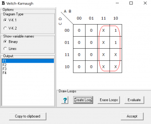
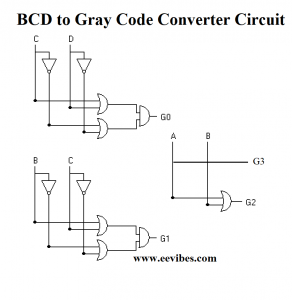
G3=A
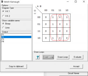
G2=A+B
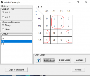
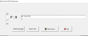
G1=B’C+BC’
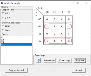
G0=C’D+CD’
The BCD to Gray Code Converter Circuit is implemented as followed. It must be noted that here each bit of gray code has been shown implemented individually.
How to Perform BCD to Gray Code Conversion?
Here is the video lecture for performing BCD to Gray code conversion
Also see
- What are the synchronous counters? Explain with an example.
- what are the half adder and full adder circuits?
- what are the half subtractor and full subtractor circuits?
- How to design a four bit adder-subtractor circuit?
- What are number systems in computer?
- Discuss the binary counter with parallel load? Explain its working with an example
- how to draw state diagram of sequential circuit?
- How to simplify a Boolean function using Karnaugh map (k-map)?
- What are the flip flops and registers in digital design?
- Define fan-in, fan-out, CMOS and TTL logic levels
- what is the Canonical form representation of Boolean function?
- What is difference between latches and flip flops?