
Arithmetic circuits
What are Arithmetic Comparison Circuits? The arithmetic circuit is a set of gates with a different arrangement of inputs for each number that must be held. The gates are associated to complete an arithmetic activity and the outputs of the gate circuit are the digits of the outcome’s addition, subtraction, and multiplication of binary numbers. Here we will discuss some circuits:
Adder Circuits:
Rules for addition of two bits are as follows:
0 + 0 = 0
0 + 1 = 1
1 + 0 = 1
1 + 1 = 0 and carry 1
There are two types of adder circuits:
Half adder:
The least difficult adder circuit for binary digits is known as a half-adder, and it permits two bits to be added, with a fundamental result and a carry bit.
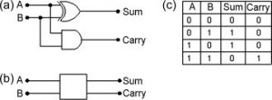
Full adder:
If the half-adder is in the IC form, then we may connect two half-adders with the help of an OR gate then it will result to provide a full adder, which allows both a carry input and as well as a carry output.

Subtractor circuit:
The rules for binary subtraction are:
0 − 0 = 0
0 − 1 = −1 (borrow 1)
1 − 0 = 1
1 − 1 = 0
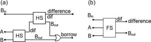
There are two types of subtractors:
- Half subtractor:
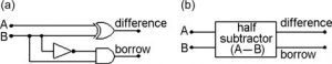
- Full subtractor:
Arithmetic comparison circuits:
One more helpful sort of arithmetic circuit looks at the relative sizes of two binary numbers. This type of a circuit is known as a comparator. This considers the design of a comparator that has two n-cycle inputs, A and B, which address the unsigned binary numbers.
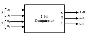
The comparator produces three outputs, known as AeqB, AgtB, and AltB. The AeqB output is a set to 1 if A and B are alike. The AgtB that is produced is 1 on the off chance that A is more larger than B, and the AltB that is produced is 1 assuming that A is smaller than B. The ideal comparator can be designed by making a reality table that determines the three outputs as elements of A and B. thus for restrained values of n, reality table is massive. The most superior methodology is to determine the comparator circuit by considering both bits of A and B two by two.
Example:
Here we will describe this by taking a simple example where n = 4. So first of all Let A = a3a2a1a0 and B = b3b2b1b0. Then characterize a lot of transitional signs such as i3, i2, i1, and i0. Each sign, ik , is 1 if the bits of A and B with a similar list are equivalent. Which is, ik = ak ⊕ bk . The comparator’s AeqB output is then given by AeqB = i3i2i1i0. The expression for the AgtB result can be determined by considering the bits of A and B in the order from the fundamental piece of the most un-fundamental piece. The principal bit-position, k, at which ak and bk vary decides if A is not exactly lesser or bigger than B. In an event if ak = 0 and bk = 1, then A < B. thus, in an event if ak = 1 and bk = 0, then A > B. The AgtB output is considered by:
AgtB = a3b3 + i3a2b2 + i3i2a1b1 + i3i2i1a0b0.
The ik signals guarantee that the digits that comes first are considered from the left to the right, of A and B that vary decide the worth of AgtB. The AltB result can be found by involving the other two outputs as:
AltB = AeqB + AgtB.
The four-cycle comparator circuit can be carried out by a logic circuit. This effort can be utilized to design a comparator for any value of n. Comparator circuits are the most rationale circuits, that can be planned or designed in many other ways.
Also read here
- Standard Chips for Digital Logic Design
- What are the Practical Aspects of Digital Circuit Design?
- What are the Transmission Gates?
- How to design a four bit adder-subtractor circuit?
- What are the Techniques for Testing Digital Circuits?
- What are the Shift and Add Multiplier Circuits?
- How to Design Counters Using Sequential Circuits?
- How to Design a 4 bit Magnitude Comparator Circuit? Explanation with examples