Testing of Digital Circuits
What are the Techniques for Testing Digital Circuits? In digital circuits, the testing of a combinational circuits are effective. for this we use different techniques like “deterministic” or “a random test set”. These are the approaches for the combinational circuits. but in sequential circuits, it’s hard for us for testing as in sequential circuits we use memory elements. So, due to memory element the circuit depends upon different states, so the sequential circuit the input is totally dependent upon the state of the circuit.
Combinational circuits can be tested by the functionality of the truth table, just like that in sequential circuits, these circuits are tested by the functionality of the state table. That implies all the checking which calls that the circuit perform all the state correctly. It seems easier but, it is harder than thought.
We know sequential circuit depend upon the memory location, so it is difficult to ascertain the circuit in a specific state. as the state variable are not observable on an external pin which is usually a case. Such that the transition is checked that it reaches to its original state destination.
This approach is useful foe small circuit but not for the practical size circuits. the true approach is that to build the sequential circuits, so they easily tested.
The techniques for the digital circuits are given as follow.
- Design for testability
- Scan path technique
Design for testability:
The synchronous sequential circuit embraces combinational circuit that implement the output and the next state function. As well as flipflop that keeps the information of state during a clock cycle. The inputs for the combinational network primary inputs from w1 through wn. The present state are from y1 to yk. Where the primary outputs are from z1 to zm. If we apply a test vector on a primary input, it would not be much harder. but the question is that how we apply a test vector on a present state input and how to observe the state output.
So, the possible way of this if we put a two-way multiplexer for a present state variable input. In this way the combinational network might the variable of the state or it might be the value of the test vector. The major drawback of this approach is the second output is directly connected to the external pin. So, it require many pins according to the state variable.
Using a connection that allows moving the test vector into the circuit one bit at a time, trading off pin demands for time it takes to run a test, is an appealing solution.
Scan path technique:
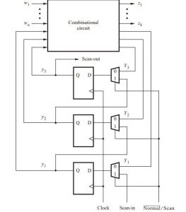
The most important technique is a scan path technique. we use multiplexers and flipflop so we can use it for the independent part of the sequential circuit or use it a shift register for testing variable. the structure for this a, we use three flipflops and two to one line multiplexer. Which connect the D output of a multiplexer, or a next state variable is corresponding to the shift register. The control signal Normal/Scan selects the active input of the multiplexer. During the normal operation the flip-flop inputs are driven by the next-state variables, Y1, Y2, and Y3. For the testing purpose of shift registers is used to scan the portion of every test variable having a present state y1, y2 and y3. And the connection of Qi is with Di+1.
So, by scanning into the flip-flops a sequence of 0s and 1s, such as 01011001 in repeated clock cycles, and checking to see if the identical pattern is scanned out, the operation of the flip-flops may be verified. By applying test vectors to w1w2 and wny1y2y3 and seeing the results that are produced on z1z2 and zmY1Y2Y3, the combinational circuit is put to the test. The process is as follows:
- normal\scan=1, when the vector test y1,y2and y3 are scanned in to the flipflop using three clock cycle.
- The w1,w2 ···wn portion of the test vector is applied as usual and the normal operation of the sequential circuit is performed for one clock cycle, by set Normal/Scan = 0 .
The diagram is as follows:
How to Test Flip-fFops?
Flip-flops can be tested by scanning them for sequences of 0s and 1s like explained above. A combinational circuit can be tested by applying test vectors to w,y1 and y2. Let’s use the random testing method, choosing any four test vectors wy1y2 = 001, 110, 100, and 111. To use the first test vector, the pattern y1y2 = 01 is scanned into the flip-flops over two clock cycles. Then for one clock cycle the circuit it is made to work in normal mode with w = 0. This basically applies a vector wy1y2 = 001 to AND-OR circuit.
The result of this test should be z = 0, Y1 = 0 and Y2 = 0. The value of z can be observed directly. The values of Y1 and Y2 are loaded into respective flip-flops and are sensed during the next two clock cycles. Like these values, another test pattern y1y2 = 10 can be scanned. self-test it takes five cycles to perform one test, but the last two cycles overlap with the second test.
The third and fourth tests are performed in the same way. Total time required for this perform all four 14-hour cycle tests. The prior method was built on the premise that the sequential circuit may be evaluated by evaluating its combination element using the methods provided in earlier parts. With a scan path device, you may test a sequential circuit by cycling through each transition shown in the status table. Simply scanning into flip-flops and evaluating the state variable that correlates to the desired state will bring the circuit into that state.
By keeping an eye on the main outputs and scanning the prize that symbolizes the desired state, the transition’s outcome can be verified. The scan path approach has the drawback of performing poorly in asynchronous situations. The flip-flops’ et and reset functions are employed in regular operation. We have already said that synchronous preset and reset are preferable.
The circuit may be evaluated if the designer chooses to utilize an asynchronous preset and reset capability and uses methods like level-sensitive scanning design.
Also read here
-
What are the CMOS Logic Gates?
-
What is the magnitude comparator circuit? Design a 3 bit magnitude comparator circuit
-
What are the synchronous counters? Explain with an example.
-
what are the half adder and full adder circuits?
-
what are the half subtractor and full subtractor circuits?
-
How to design a four bit adder-subtractor circuit?
-
What are number systems in computer?
-
Discuss the binary counter with parallel load? Explain its working with an example
-
how to draw state diagram of sequential circuit?
-
How to simplify a Boolean function using Karnaugh map (k-map)?
-
What are the flip flops and registers in digital design?
-
Define fan-in, fan-out, CMOS and TTL logic levels
-
what is the Canonical form representation of Boolean function?
-
What is difference between latches and flip flops?