what are the half subtractor and full subtractor circuits?
what are the half subtractor and full subtractor circuits? The design of an arithmetic logic unit requires many functions to implement that are: adders, subtractors, multipliers, and some logical operations as well. While processing the binary information there might be need to subtract the numbers. There are two basic subtractor circuits in digital logic design. They are
- Half subtractor
- Full subtractor
What is the half subtractor?
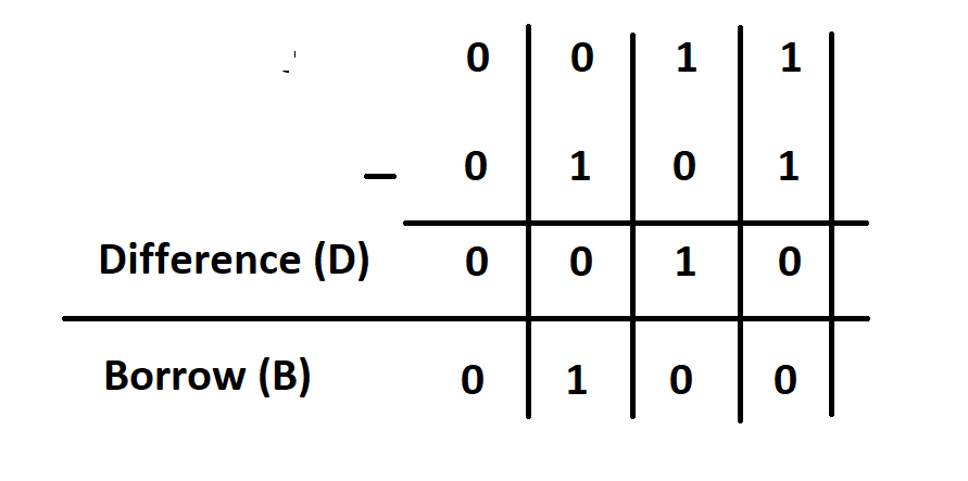
A half subtractor is a circuit that subtracts two bits x and y (x-y) and the resultant consists of two bits: difference and borrow.
There are four possibilities while subtracting two bits that are
Truth table for half subtractor
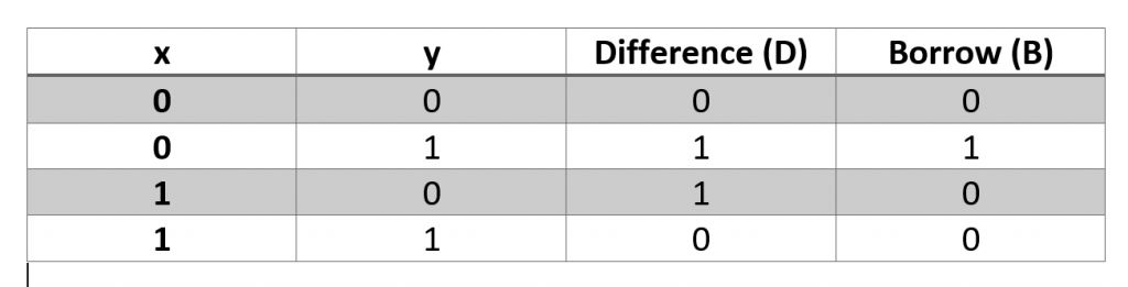
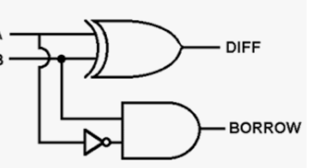
Here x-y is performed. From truth table is can be noticed that difference value is equal to 1 only when there are distinct inputs. When both inputs are same then difference value is equal to 0. Which is exactly like XOR gate behavior. So difference function can be implemented using XOR gate.
Difference=x⊕y
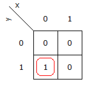
if k-map is constructed for the difference output, the same expression is obtained.
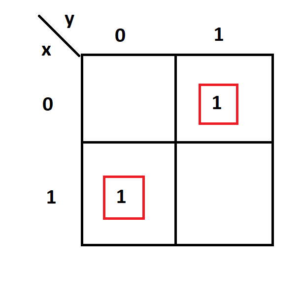
Only minterm 1 and 2 are present that is why
Difference=x’y+xy’
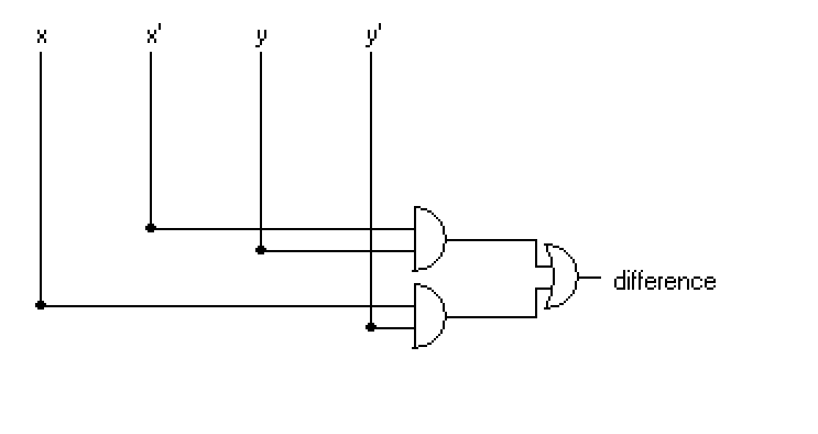
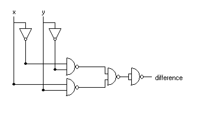
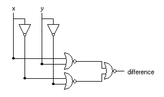
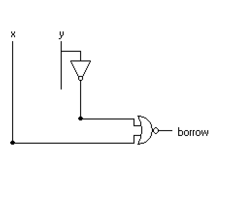
Complete circuit of half subtractor
What is the full subtractor circuit?
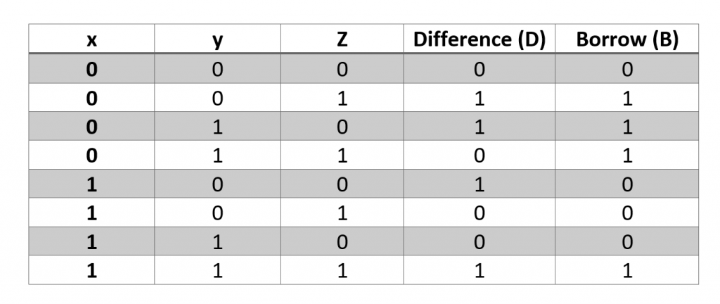
A full subtractor is a circuit that subtracts three binary bit (x-y-z) where z is the borrow during subtraction. Lets consider the three bit combination then truth table can be constructed as
K-map for full subtractor (difference)
difference=xy’z’+x’y’z+xyz+xyz’
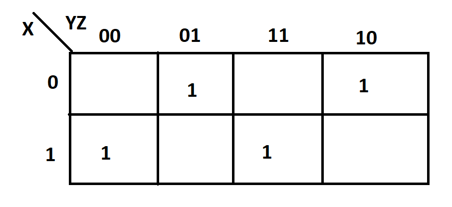
K-map for full subtractor (borrow)
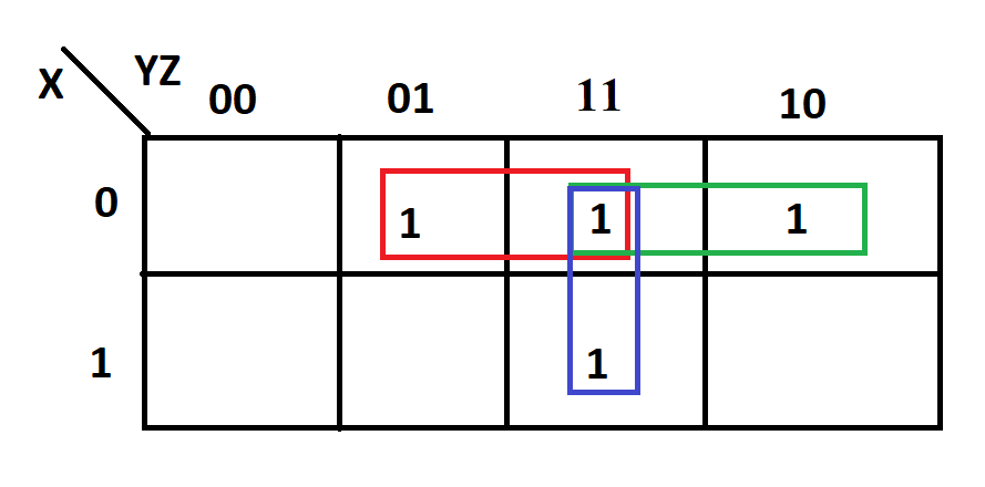
borrow=x’z+x’y+yz
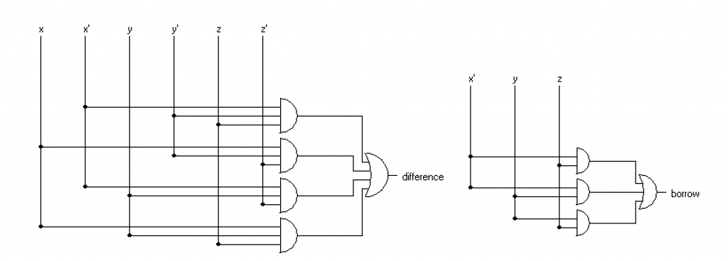
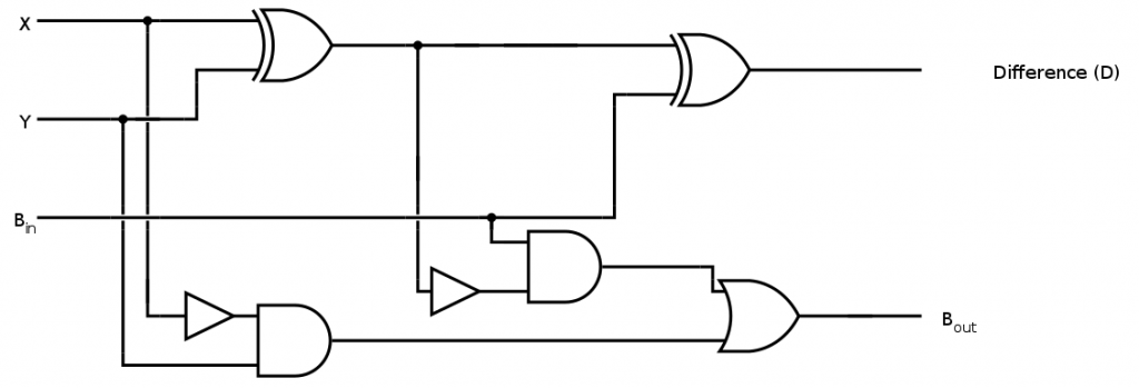
Logic diagram of full subtractor (borrow and difference)
video lecture for half subtractor and full subtractor circuits
video lecture for half subtractor and full subtractor circuits
Lab manual of designing adder and subtractor circuit
lab manual 5 digital logic design adder and subtractor circuit
related topics
- How to design a four bit adder-subtractor circuit?
- What are number systems in computer?
- Discuss the binary counter with parallel load? Explain its working with an example
- how to draw state diagram of sequential circuit?
- How to simplify a Boolean function using Karnaugh map (k-map)?
- What are the flip flops and registers in digital design?
- Define fan-in, fan-out, CMOS and TTL logic levels
- what is the Canonical form representation of Boolean function?