
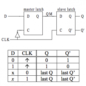
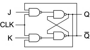
What happens when you apply asynchronous inputs to flip flops? Regardless of the state of the clock input, asynchronous inputs on a flip flop have control over the outputs (Q and not-Q).
These inputs are referred to as clear and present (PRE) (CLR). The clear input resets the flip flop and clears all of the I/P while the current input pushes it to a set state. It is also feasible to determine a J-K flip flop’s outputs to an invalid state by using the asynchronous input.
Effect of Switch Debouncing
Everyone is familiar with how a switch or push button operates—you just press it to change its state. The majority of the items that switches are used to control or represent in electronics take the form of various voltage levels, making the system binary, that is, either ON or OFF and in voltage levels High or Low. Therefore, these voltage levels (for example, 5 Volts = High = ON = closed circuit and 0 Volts = Low = OFF = open circuit) aid in representing the binary logic of 0s (zeros) and 1s (ones).

However, a lot happens behind the straightforward push buttons on our keyboards and other gadgets. A basic button consists of only two metal contacts that come into contact when the user presses the button. The underlying circuit is then completed by these metal contacts, which also notify the sensor component—usually a micro-controller—that the button has been pushed.
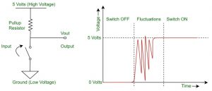
The physical process of contacting metal contacts is different; once the user presses them, the metal contacts bounce off one another, turning the switch on and off for a period of time. As a result, several button presses from a single action may be registered provided the detecting device is sensitive enough. This may impede several procedures and cause faults into the system you are utilizing.
Therefore, the idea of switch debounce is required to prevent this incorrect perception of button push. This aids in accurately recording the switch’s operation. Both software programming and the usage of hardware circuitry may be used to produce switch debounce. Let’s take a quick look at these techniques.
Software Switch Debouncing:
Using a variety of algorithms and filters, this technique gets rid of the switch’s bouncing state effect. A shift register and counters may be used by the programmer to create an algorithm that will record the switch’s state after a delay. Another approach is to apply filter algorithms to the switch’s sampled input and then use the digital filter’s output to infer the switch’s state. If all of this isn’t done properly, the program may become somewhat inefficient, which will contribute to performance delays.
Hardware Switch Debouncing:
In this category, you’ll find a variety of circuit designs that may be utilized to completely eliminate the switch debouncing effect at the hardware level. The many kinds of circuits utilized include:
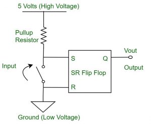
S-R Flip Flop Latch circuit use. When the circuit is added to the switch’s output section, the output state will continue to be the voltage level of the input. Latching on the input as a result of a state change. Although this approach is helpful, it makes the straightforward circuit bulkier.
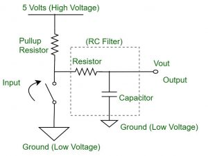
R-C circuit use. In this circuit, a resistor and capacitor circuit work together to function as a filter, reducing output jitter for the switch.
use of specialised ICs. Different integrated circuits that are available on the market are designed expressly to stop switches from bouncing. These use combination circuits to get rid of the switch’s output fluctuations.
Also read here:
- How to design a 4 bit magnitude comparator circuit? Explanation with examples
- What is the magnitude comparator circuit? Design a 3 bit magnitude comparator circuit
- What are the synchronous counters? Explain with an example.
- what are the half adder and full adder circuits?
- what are the half subtractor and full subtractor circuits?
- How to design a four bit adder-subtractor circuit?
- What are number systems in computer?
- Discuss the binary counter with parallel load? Explain its working with an example
- how to draw state diagram of sequential circuit?
- How to simplify a Boolean function using Karnaugh map (k-map)?
- What are the flip flops and registers in digital design?
- Define fan-in, fan-out, CMOS and TTL logic levels
- what is the Canonical form representation of Boolean function?
- What is difference between latches and flip flops?