Portable Ultrasonic Range Meter
Design an Portable Ultrasonic Range Meter using Arduino Sound is an event that results from vibration. Sound is seen as a mechanical wave that carries mechanical energy. In order to transfer this power between the sender and the receiver, the presence of a communication device is required. The contents can be solid, liquid or gaseous. Sound energy travels by causing distortion in the way it travels and this is called scattering of sound waves. Under normal circumstances, the sound speed is 330m / s. SONAR or Sound Navigation and Ranging Route is a measure of distance communication that is commonly used on submarines. In this process, the high frequency sound is transmitted by the transmitter and the echo displayed from the object is captured by the receiver. As the speed of the sound wave is known, by measuring the travel time, the distance between the source and the target can be calculated. Depending on the volume of the sound wave, SONAR can be either Infrasonic or Ultrasonic. Ultrasonic sensors produce sound waves that are higher than audible wavelengths (20Hz to 20 KHz) i.e. more than 20 KHz. In the case of an infrasonic sensor, the frequency of the sound wave is less than 20Hz.In this project, a Portable Ultrasonic Range Meter is developed that can be used to measure target distance in a non-communicative way. The project is based on Arduino, Ultrasonic sensor and LCD display.
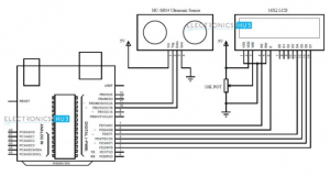
Circuit Diagram:

Circuit Explanation:
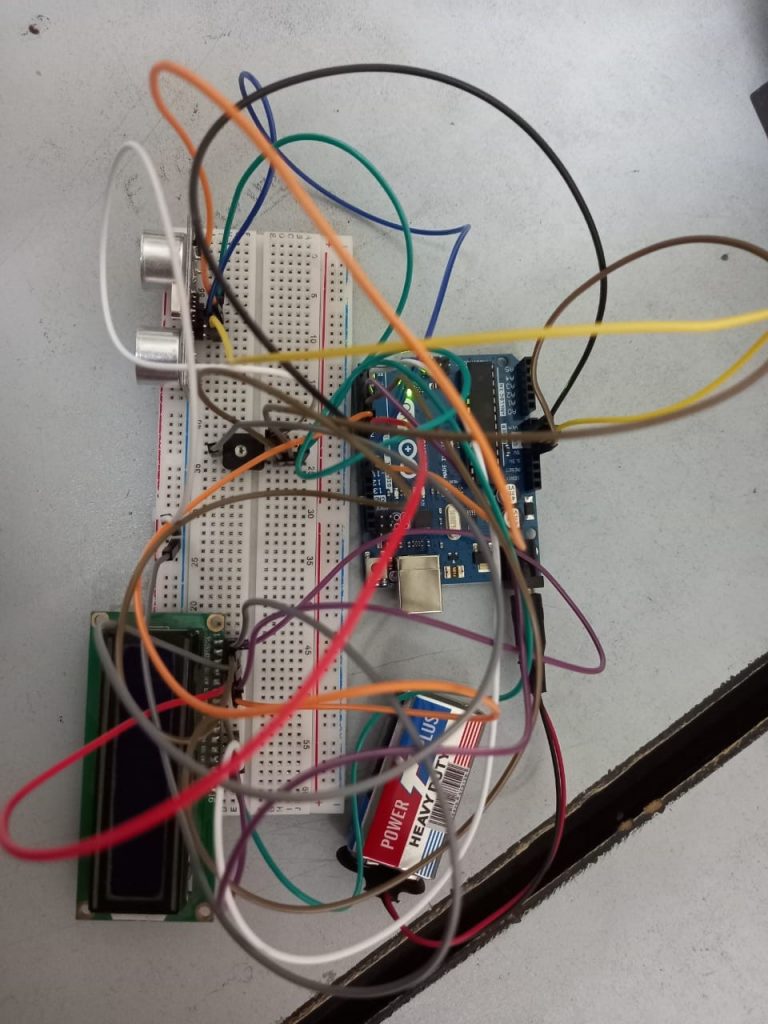
The circuit contains the Arduino Uno, which is the project brain, the Ultrasonic sensor and the LCD display for immediate results. The circuit design is very simple and is described below.
Of the 14 I / O PINs in Arduino, we use 8 pins for this project. 2 pins are used for the Ultrasonic sensor and the other 6 pins are used to control the LCD.
The 4 Ultrasonic sensor pins are Vcc, Gnd, Trig and Echo. Trig is connected to Arduino’s Pin 11 and the Echo is connected to Pin 10. In the case of Arduino, PINs 10 and 11 are input and output respectively. Pins 15 and 16 (LED + and LED-) for LCD rear light pins. Connected to Vcc and Gnd respectively (not shown in the circuit diagram).
Four LCD data pins are used to display information. 11, 12, 13 and 14 LCD pins (D4 – D7) are connected to 5, 4, 3 and 2 pins in Arduino.
The RS and E (pins (4 and 6) pins of the LCD are connected to Arduino pins 7 and 6 respectively while the RW (pin 5) is connected to the ground. Anchors 1 and 2 (Vss and Vdd) are connected to the ground and Vcc respectively. To control the brightness of the LCD display, PIN 3 (VE) LCD is connected to the 10 KΩ POT filter and other POT terminals are connected to Vcc and Gnd.
Components Required:
- Arduino Uno
- Ultrasonic Sensor HC-SR04
- 16X2 LCD Display
- 10KΩ Potentiometer
Explanation:
HC-SR04 is a type of ultrasonic sensor that uses sonar to detect the object’s distance from the sensor. It provides an outstanding range of contact acquisitions with high accuracy and stable learning. It combines two modules such as the ultrasonic transmitter & receiver. This sensor is used for a variety of applications such as location and speed measurement, burglar alarms, medical, sonar, humidity input, wireless charging, non-destructive testing, and ultrasonography.
This sensor includes four pins and the pin configuration of this sensor is discussed below.
- Pin1 (Vcc): This pin provides a +5V power supply to the sensor.
- Pin2 (Trigger): This is an input pin, used to initialize measurement by transmitting ultrasonic waves by keeping this pin high for 10us.
- Pin3 (Echo): This is an output pin, which goes high for a specific time period and it will be equivalent to the duration of the time for the wave to return back to the sensor.
- Pin4 (Ground): This is a GND pin used to connect to the GND of the system.
HC-SR04 sensor applications include the following,
- This sensor is used to measure speed and direction between two objects.
- Used for wireless charging.
- Medical ultrasound.
- This is used to detect objects and avoid obstacles using robots such as biped, navigating, avoiding obstacles, etc.
- Measuring depth.
- This sensor is used to align objects around the sensor by rotating it.
- Non-destructive testing.
- By using this depth of sensor holes, wells can be measured by transmitting waves to the water.
- Embedded system.
- Burglary alarms.
Working Portable Ultrasonic Range Meter
Ultrasonic sensor is the main module in the frequency meter range. The ultrasonic sensor contains an ultrasound transmitter and receiver. The transmitter transmits sonic pulses of 8 pulses at 40 KHz frequencies.
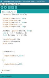
This signal strikes the target and the echo is detected by the recipient module. By measuring the time between the events to send a heartbeat and getting an echo, the distance can be calculated. The ultrasonic sensor used in this project is HC-SR04. It can be used to measure a distance of 2cm to 400cm with accurate reading. The sensor module contains 4 PINs: Vcc, Gnd, Trig and Echo. When the Trig pin is high for about 10µs, the ultrasonic sensor sends ultrasound signals. The Echo PIN is high from the time you send the signal and receive it.
This is the time when the top Echo signal is calculated by Arduino in code and converted to a distance in inches. The same data is displayed on the LCD.
Arduino continuously sends the Trig signal and the target distance can be continuously measured without delay.
As the power requirement of the circuit is very small, the whole system can be powered by a 9V battery and can be used as a Portable Range Meter.
Procedure:
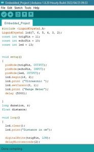
- Firstly, starting with the most important thing that is code of our project.
- After writing the code we compiled using Arduino Software.
- After successful build we saved the file
- Then we made connections according to the circuit diagram.
- After a complete connection, we verified it again
- Then we uploaded the success built of program on Arduino board.

Video of Portable Ultrasonic Range Meter
Related Projects
-
Serial communication project using PIC microcontroller
-
Design of smart electronic voting machine using Arduino
-
How to control the speed and direction of DC motor using Arduino?
-
How to Display on 8×8 Dot Matrix LED Using Arduino(UNO)?
-
How to Design RGB Mood Lamp using Arduino?
-
Serial Temperature Sensor Project using Arduino
-
How to design an LED Flasher on Arduino Board
-
Design of Traffic Light Control system using Arduino
-
Arduino Project: How to control the speed of DC motor?
-
Arduino Project: Send Command with Serial Communication
-
Arduino Project: LED Fire Effect