
Binary Multiplier
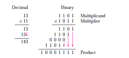
What are the Binary Multiplier Circuits? A binary multiplier is a circuit that is used for the multiplication of two numbers A and B having bits m and n respectively. Two terms that are used in multiplication are: multiplier and a multiplicand. Let’s assume that here A is multiplier and B is the multiplicand. During multiplication, each bit of multiplicand is multiplied with each bit of multiplier starting from the right hand side or from the least significant bit. It will result in multiple partial products. Finally we add up all these partial products in order to obtain the final product result.
Multiplication of m-bit multiplier with n-bit multiplicand
From the general concept of the multiplication, we can say that multiplying two bits is equivalent to their AND operation. So, for generating the partial products we will be using multiple AND gates and for adding the partial products, we will use binary adders. Lets us assume that we have to multiply an m-bit number with an n-bit multiplicand. For this we will need (m×n) number of AND gates for generating the partial products, (m-1) n-bit adders for adding the partial products for generating product of (m+n) bits.
2-bit by 2-bit Binary Multiplier Circuit
The design procedure involves in determining the number of AND gates and required number of adders. Since m and n are equal to 2. So, 4 AND gates are required with 2-half adders for producing product of 4 bits.
A=A1 A0
B=B1 B0
B1 B0
A1 A0
___________________
B1A0+A0 B0
B1A0+ A0 B0+ ×
___________________
B1A0+A0 B0+B1A0+ A0 B0
___________________
A=1 1 (3)
B=0 1 (1)
_______________
1 1
0 0 ×
_______________
0 1 1 (3)
_______________
The circuit for 2-bit multiplier is shown in the figure below.
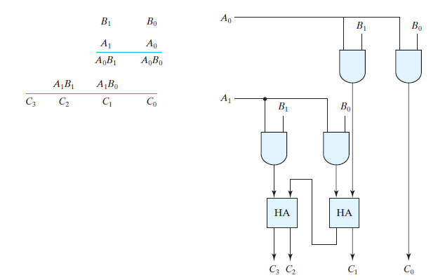
It can be seen that A0 is multiplied with each bit of B by using AND gate for generating first partial product B1A0 A0 B0. The least significant bit is passes as it is as it does not need to be added. Then next partial product is obtained by multiplying A1 with each bit of B again using AND gate. This will result in second partial product B1A0, A0 B0. Then we will use half adders for adding these partial products. Usually, there are more bits in the partial products and it is necessary to use full adders to produce the sum of the partial products. Note that the least significant bit of the product does not have to go through an adder, since it is formed by the output of the first AND gate.
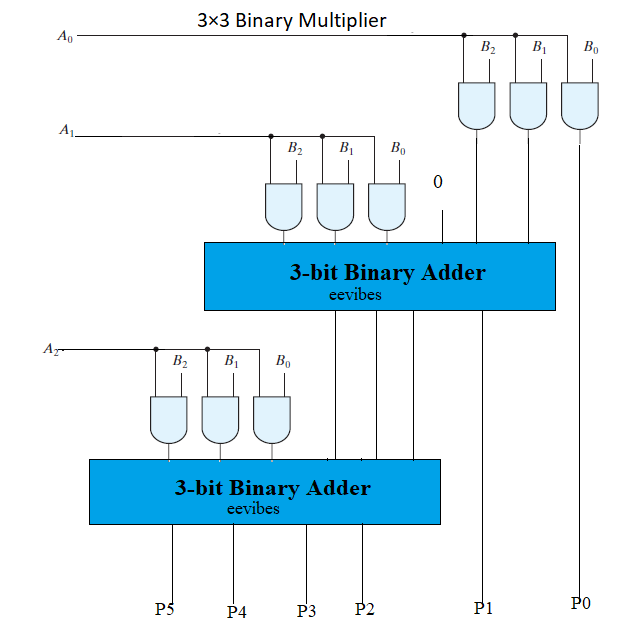
3-bit by 3-bit Binary Multiplier Circuit
Now, let us assume that we want to multiply two numbers having 3-bits each. There will total of 9 AND gates, with 2 3-bit adders for resulting product of 6-bits.
B2B1 B0
A2 A1 A0
_____________________________
A0 B2+B1A0+A0 B0
A1B2+B1A0+ A0 B0 ×
A2B2+B1A2+ A2B0 × ×
___________________________________________
A2B2+B1A2+A1B2+A2B0 +B1A0+B2A0+A0 B0+B1A0+ A0 B0
A=1 1 1 (7)
B=0 1 1 (3)
____________________
1 1 1
1 1 1 ×
0 0 0 × ×
________________________________
1 0 1 0 1 (16+4+1=21)
________________________________
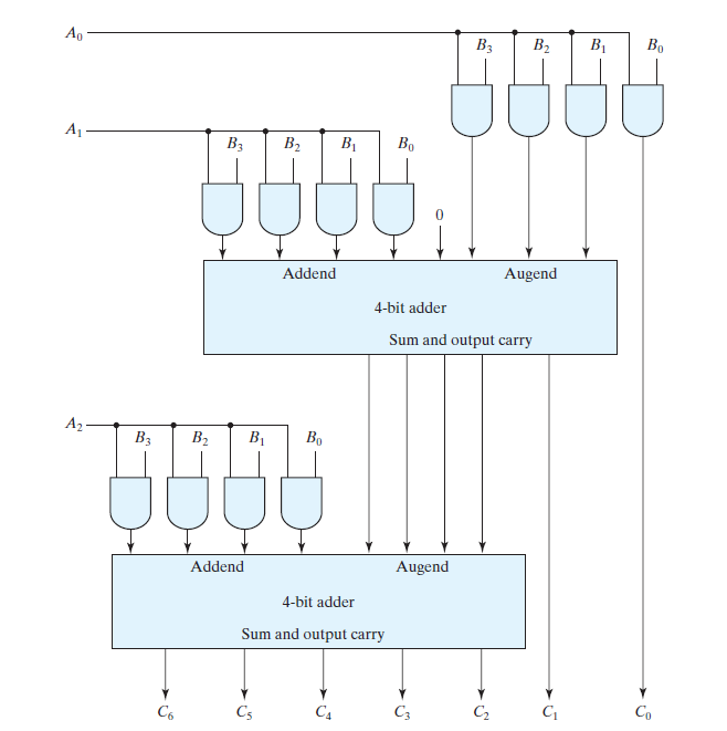
4-bit by 3-bit Binary Multiplier Circuit
Similarly for designing a multiplier circuit having multiplicand bits=4 and multiplier bits=3, we will need 12 AND gates, 2 4-bit adders and the resultant will have 7 number of bits in it. The circuits diagram for (3X4) multiplier is shown in the figure below.
Example of 4-bit by 4-bit Multiplier
Also read here
-
What are the CMOS Logic Gates?
-
What is the magnitude comparator circuit? Design a 3 bit magnitude comparator circuit
-
What are the synchronous counters? Explain with an example.
-
what are the half adder and full adder circuits?
-
what are the half subtractor and full subtractor circuits?
-
How to design a four bit adder-subtractor circuit?
-
What are number systems in computer?
-
Discuss the binary counter with parallel load? Explain its working with an example
-
how to draw state diagram of sequential circuit?
-
How to simplify a Boolean function using Karnaugh map (k-map)?
-
What are the flip flops and registers in digital design?
-
Define fan-in, fan-out, CMOS and TTL logic levels
-
what is the Canonical form representation of Boolean function?
-
What is difference between latches and flip flops?