Types of Finite State Machine
In this article I will discuss Mealy and Moore Type FSM for Serial Adder. But let us just see first that there are two main types of finite state machines (FSM)
Mealy type
Moore type
Mealy type FSM for serial adder:
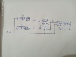
As we know that mealy model output is based on both present state and the input of the sequential circuits. Let A and B be two unsigned numbers that have to be added to produce sum S. We perform a task of serial addition y adding two inputs A and B for serial adder. For addition we perform a cycle for bit configuration by one by one. It includes three shift registers that are used to hold A, B and S. Then in each clock cycle, a pair of bits is added by the adder FSM, and the end of the cycle the resulting sum bit is shifted into the S register. We use positive-edge-triggered flip-flops in which changes take place soon after the positive edge of the clock, depending on the propagation delays within the various flip-flops. At this time of propagation the contents of all three shift registers are shifted to the right; this shifts the existing sum bit into sum S bit, and it presents the next pair of input bits a and b to the adder FSM.

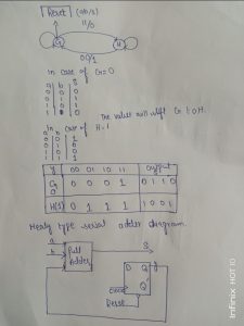
For the FSM model the table depends on the given equation,
Y=ab+ ay+ by
For S the equation will be the XOR of inputs and output.
The next state is depending on the two present states G and H having value 0 and 1. In state G the input valuation 00 will produce s = 0 and the FSM will remain in the same state. For input valuations 01 and 10 the output will be s = 1 and the FSM will remain in G. But for 11, s= 0 is generated, and the machine moves to state H. In state H valuations 01 and 10 cause s = 0, while 11 cause s = 1. In all three of these cases, the machine remains in H. However, when the valuation 00 occurs, the output of 1 is produced and a change into state G takes place.

Moore type FSM for serial adder:
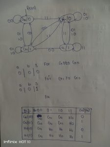
As we know that Moore’s model output is based on its present state. In mealy model we used only 2 present states but in Moore’s model we required more than 2 states G, G0 and H or H0.
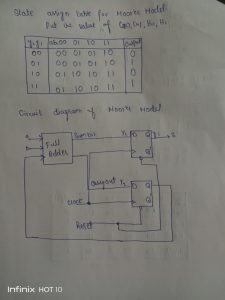
Y1 is simply the XOR of a, b and y2
Y2=ab+ay2+by2
S=y1


The difference between the Mealy and Moore’s model is that the Moore’s model output s passed through an extra flip flop and there is a delay in clock cycle.
For more detail check
what is the difference between Mealy and Moore models?
Also check
-
Discuss the Several System Design Examples using ASM Charts Clock
-
What are the CMOS Logic Gates?
-
How to design a 4 bit magnitude comparator circuit? Explanation with examples
-
What is the magnitude comparator circuit? Design a 3 bit magnitude comparator circuit
-
What are the synchronous counters? Explain with an example.
-
How to design a 4 bit magnitude comparator circuit?
-
what are the half adder and full adder circuits?
-
what are the half subtractor and full subtractor circuits?
-
How to design a four bit adder-subtractor circuit?
-
What are number systems in computer?
-
Discuss the binary counter with parallel load? Explain its working with an example
-
how to draw state diagram of sequential circuit?
-
How to simplify a Boolean function using Karnaugh map (k-map)?
-
What are the flip flops and registers in digital design?
-
Define fan-in, fan-out, CMOS and TTL logic levels
-
what is the Canonical form representation of Boolean function?
-
What is difference between latches and flip flops?