Divider Circuits
What are the Divider Circuits? In binary division two binary numbers of base 2 can divided using basic binary division rule. The steps in binary division rule are:
- First compare divisor with dividend.
- Then bring down the next number from the dividend portion and do the step 1 process again.
Repeat the process until the remainder becomes zero by comparing the dividend and the divisor value.
Explanation
To begin, consider dividing 11000101 by 1010. Just as in decimal division, we can compare the four most significant bits of the dividend (i.e., 1100) with the divisor to find the first digit of the quotient. We are working with binary numbers, so the digits of the quotient can be either zero or one.
Since 1100 is greater than 1010, the first digit of the quotient will be one. The obtained digit must be multiplied by the divisor and the result must be subtracted from the dividend. Now, we should write the next bit of the dividend (shown in red) to the right of the difference and continue the procedure just as we do in a decimal division. Hence, we obtain
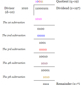
The above example shows the decimal equivalent of the parameters as well as the letters used to represent them. We can verify the calculations by evaluating z=q*d+s and that s<d.
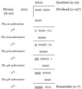
To get a better insight into the implementation of the division algorithm, we rewrite the above example as:
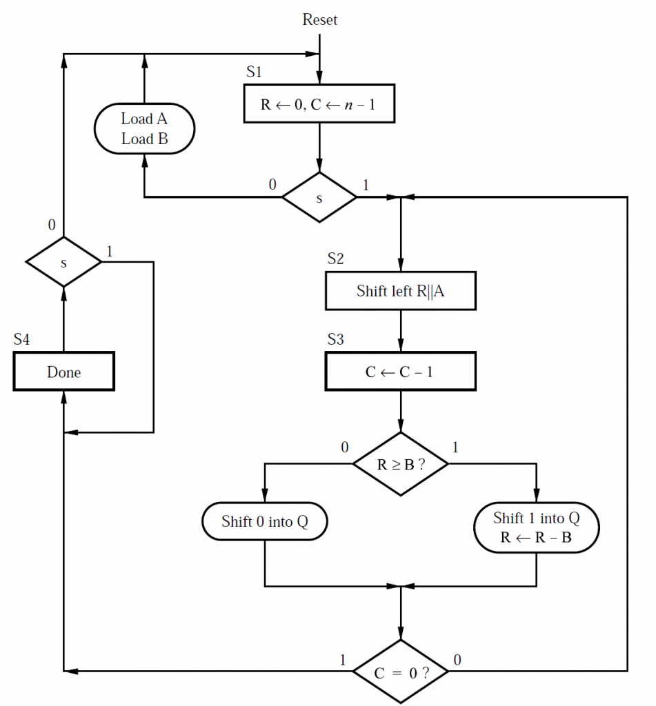
The Division Algorithm
With the block diagram of Figure 2, we need to perform the following operations repeatedly:
Load the dividend and the divisor to the Z and D registers, respectively. Reset z8z8 to zero. Besides, set the value of the iteration counter to zero.
If z8z7z6z5z4<d3d2d1d0z8z7z6z5z4<d3d2d1d0, go to step 3 otherwise set a flag to indicate the overflow condition and end the algorithm.
Shift the Z register to the left by one bit. The shift operation will vacate the LSB of the Z register. This empty memory location will be used to store the quotient bit obtained in the next step.
Compare z8z7z6z5z4z8z7z6z5z4 with d3d2d1d0d3d2d1d0:
(a) If z8z7z6z5z4≥d3d2d1d0z8z7z6z5z4≥d3d2d1d0, set the LSB of the Z register to one and update the five MSBs of the Z register with the difference z8z7z6z5z4−d3d2d1d0z8z7z6z5z4−d3d2d1d0.
(b) If z8z7z6z5z4<d3d2d1d0z8z7z6z5z4<d3d2d1d0, set the LSB of the Z register to zero and keep the five MSBs of the Z register unaltered.
Increase the value of the counter by one. If the counter is equal to four, end the algorithm otherwise go to step 3.
VHDL code for Divider Circuit
1 library IEEE;
2 use IEEE.STD_LOGIC_1164.ALL;
3 use IEEE. NUMERIC_STD.ALL;
4 entity Divider is
5 Port (clk, reset : in STD_LOGIC;
6 start : in STD_LOGIC;
7 m : in STD_LOGIC_VECTOR (15 downto 0); — Input for dividend
8 n : in STD_LOGIC_VECTOR (7 downto 0); — Input for divisor
9 quotient : out STD_LOGIC_VECTOR (7 downto 0); — Output for quotient
10 remainder : out STD_LOGIC_VECTOR (7 downto 0); — Output for remainder
11 ready, ovfl : out STD_LOGIC); — Indicates end of algorithm and overflow condition
12 end Divider;
13 architecture Behavioral of Divider is
14 — Type for the FSM states
15 type state_type is (idle, shift, op);
16 — Inputs/outputs of the state register and the z, d, and i registers
17 signal state_reg, state_next : state_type;
18 signal z_reg, z_next : unsigned(16 downto 0);
19 signal d_reg, d_next : unsigned(7 downto 0);
20 signal i_reg, i_next : unsigned(3 downto 0);
21 — The subtraction output
22 signal sub : unsigned(8 downto 0);
23 begin
24 –control path: registers of the FSM
25 process(clk, reset)
26 begin
27 if (reset=’1′) then
28 state_reg <= idle;
29 elsif (clk’event and clk=’1′) then
30 state_reg <= state_next;
31 end if;
32 end process;
33 –control path: the logic that determines the next state of the FSM (this part of
34 –the code is written based on the green hexagons of Figure 3)
35 process(state_reg, start, m, n, i_next)
36 begin
37 case state_reg is
38 when idle =>
39 if ( start=’1′ ) then
40 if ( m(15 downto 8) < n ) then
41 state_next <= shift;
42 else
43 state_next <= idle;
44 end if;
45 else
46 state_next <= idle;
47 end if;
48 when shift =>
49 state_next <= op;
50 when op =>
51 if ( i_next = “1000” ) then
52 state_next <= idle;
53 else
54 state_next <= shift;
55 end if;
56 end case;
57 end process;
58 –control path: output logic
59 ready <= ‘1’ when state_reg=idle else
60 ‘0’;
61 ovfl <= ‘1’ when ( state_reg=idle and ( m(15 downto 8) >= n ) ) else
62 ‘0’;
63 –control path: registers of the counter used to count the iterations
64 process(clk, reset)
65 begin
66 if (reset=’1′) then
67 i_reg <= ( others=>’0′ );
68 elsif (clk’event and clk=’1′) then
69 i_reg <= i_next;
70 end if;
71 end process;
72 –control path: the logic for the iteration counter
73 process(state_reg, i_reg)
74 begin
75 case state_reg is
76 when idle =>
77 i_next <= (others => ‘0’);
78
79 when shift =>
80 i_next <= i_reg;
81
82 when op =>
83 i_next <= i_reg + 1;
84 end case;
85 end process;
86 –data path: the registers used in the data path
87 process(clk, reset)
88 begin
89 if ( reset=’1′ ) then
90 z_reg <= (others => ‘0’);
91 d_reg <= (others => ‘0’);
92 elsif ( clk’event and clk=’1′ ) then
93 z_reg <= z_next;
94 d_reg <= d_next;
95 end if;
96 end process;
97 –data path: the multiplexers of the data path (written based on the register
98 –assignments that take place in different states of the ASMD)
99 process( state_reg, m, n, z_reg, d_reg, sub)
100 begin
101 d_next <= unsigned(n);
102 case state_reg is
103 when idle =>
104 z_next <= unsigned( ‘0’ & m );
105
106 when shift =>
107 z_next <= z_reg(15 downto 0) & ‘0’;
108 when op =>
109 if ( z_reg(16 downto 8) < (‘0’ & d_reg ) ) then
110 z_next <= z_reg;
111 else
112 z_next <= sub(8 downto 0) & z_reg(7 downto 1) & ‘1’;
113 end if;
114 end case;
115 end process;
116 –data path: functional units
117 sub <= ( z_reg(16 downto 8) – unsigned(‘0’ & n) );
118 –data path: output
119 quotient <= std_logic_vector( z_reg(7 downto 0) );
120 remainder <= std_logic_vector( z_reg(15 downto 8) );
121 end Behavioral;
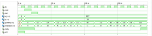
The ISE simulation for the code
Also read here
- What Types of CAD Tools are Used for Designing a Digital System?
- What happens when you apply asynchronous inputs to flip flops?
- How to design a 4 bit magnitude comparator circuit? Explanation with examples
- What is the magnitude comparator circuit? Design a 3 bit magnitude comparator circuit
- What are the synchronous counters? Explain with an example.
- what are the half adder and full adder circuits?
- what are the half subtractor and full subtractor circuits?
- How to design a four bit adder-subtractor circuit?
- What are number systems in computer?
- Discuss the binary counter with parallel load? Explain its working with an example
- how to draw state diagram of sequential circuit?
- How to simplify a Boolean function using Karnaugh map (k-map)?
- What are the flip flops and registers in digital design?
- Define fan-in, fan-out, CMOS and TTL logic levels
- what is the Canonical form representation of Boolean function?
- What is difference between latches and flip flops?