Introduction to Modern Digital Circuits
What are the modern digital circuits? Digital circuits are now an increasingly integral part of modern life. The digital circuit is now our computer, our cell phone, our car, our television, our watch. You can find digital circuits not out of your sight, new applications are constantly evolving. Unexpectedly, this is a very recent phenomenon. In the 1960’s, digital circuits were just beginning to look for commercial applications, and in everyday life, they rarely competed with anyone. By the mid-1970s, pocket meters became popular among scientists, engineers, and students, and by the mid-1980s, personal computers were widely used.
The use of digital circuits has grown rapidly since then and it is difficult to survive without them today. There are two great inventions that have revolutionized the digital world. The first was the invention of the transistor in the late 1940s and the second was the invention of the integrated circuit in the late 1950s.
Transistors are now integral building materials used to create digital circuits, and integrated circuit technology is a manufacturing process that allows multiple transistors to interconnect to create simulated, complex circuits. 2 Although there were only a few transistors in the early integrated circuit, the progress of production now allows us to build billions of transistors on silicon chips. A feature of a digital circuit is that it uses voltage և currents to represent logical values, usually expressed as “0” “1”.
It is possible that since digital circuits represent logical values, it is possible to combine the basic blocks of a digital circuit by applying only logical principles, which is useful. How circuits eventually behave is much simpler than physics formulas. This gives digital circuits a kind of modularity that is not present in ordinary analog circuits. It is modularity that allows us to create complex mental circuits that do what we expect of them to be reliable and consistent.
This does not mean that we can completely avoid the laws of physics. Another big reason why digital circuits are so successful is the ability of programmers to program, which is the most powerful digital circuit. What makes it so strong is its extraordinary flexibility, the key to that flexibility is programmability. Although the processor is only a circuit, it can be programmed to perform various functions. This programmability means that a single device can perform many different tasks. Thus, the same processor can be used on a wristwatch or meter to perform different tasks at different times, as evidenced by the expansion of mobile applications.
Also read here:
How to design a four bit adder-subtractor circuit?
Gates and Flip Flop
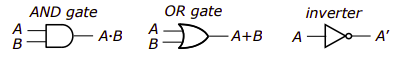
AND Gate Logic and its both input. Second, if two inputs are ‘1’, the output is ‘1’; Otherwise the output will be zero. Different and in action we use the sign ‘·’. Similarly, or the output of the gate is ‘1’ from the input of ‘1’; Output Output ‘0’. End with ‘+’, the output of the inverter input is only the end of its input.
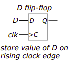
A flip-flop is a device that stores data and has the same logical value. There are actually a variety of flip-flops to choose from, but the most common is the simple D flip-flop shown here. The D flip-flop has two inputs,
data entry (labeled “D”) and clock input (labeled “> C”). The output (marked ‘Q’) is always equal to the value stored in the flip-flop. If the clock input changes from “0” to “1”, the stored value changes. More precisely, with each increasing clock transmission, the value displayed on the input D is stored in a flip-flop. This price remains the same until the next emerging watch movement.
Also read about different types of flip-flops here:
What are the SR latch and JK flip flop?
How are the digital circuits designed?
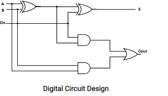
After all, a digital circuit is just a combination of ports and flip flops connected to each other. So the goal of the design process is to decide which ports and flip flops to use and how to attach them to make a circuit that works the way you want it to. One way to describe a circuit is to use an ischemic diagram that shows a group of parts, which are connected to each other by a line drawn on one side. The idea of digital burning with artisanal sketches came about in preparation for burning medium-sized wallpaper, and in most digital burning projects it was similar to the 1980s. Digital has improved, computer-aided design tools have evolved to match the cost of manual labor to define circuits and identify them accurately. Well done.
Early computer-aided design developers replaced hand-drawn images with images created with image editors. It wasn’t easy for the developer to work with, but he recognized the automation of the first steps needed to turn a developer’s logic image into an array of transistors on an integrated circuit board.
A major step forward was the introduction of specific hardware languages that would allow circuit developers to define circuits in a language similar to the advanced programming languages used for computer software. While the overall outcome of the design process was the circuits that Gates and Flip Flops had, the use of the term advanced allowed the designers to re-examine how they wanted to implement their circuit projects. , and pay less attention to detail. How are the parts of the circle related to each other? A simulator is a piece of software that simulates the nature of a circuit and provides a visual representation that allows the operator to observe how internal signals change as the circuit moves.
Simulators are the most powerful tools that allow developers to see the effects of faults in their circuit design and point those faults to their root cause.
Programmable Processors
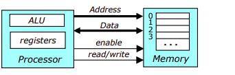
Memory can be thought of as a set of protected areas, each marked by a geographical number, called its geographical location. Each dot can store a certain number of fixed lengths (in independent processes it is 32 or 64 bits). Memory numbers are also long numbers and the number of notes is limited by the number of bits used to refer to the number. There are some clues that remain in the memory. To restore the value stored in memory, the creator raises the memory (using the input signal) to raise the read / write mark and search for the desired memory on the number lines.
. The viewer responds by placing the property stored at this location in this data line. To write values to memory, the user memorizes, reduces read / write symbols, is instructed where to write the number lines, etc. the data values to write the data lines. The manufacturer added some storage areas called files.
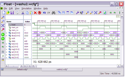
Signal names appear on the left side of the window and the main section shows how the values of different signals change over time. The first few signals are the ones that connect to the processor and the memory. By looking at these signals, we can see that values are being transferred between the processor and specific memory locations.
For example, the first time when the activation signal is high, the decimal hex value 1000 is read from position 0, but the third time when capacity is high, the value 0000 is written to position 0011. The labeled signal condition indicates what is in the processor doing. At every point of time. Remember to take repeated instructions. One guide follows each pair of subtitles, although only the first two or three letters of the tutorial name will appear in this view form. The four programs are the program counter (PC) processor, the instruction program, the indirect address program and the reservoir. They are visible at the bottom of the window. As we take an in-depth study of the processor, we’ll see how programs are used to implement a Washu-2 alien bring-and-execute cycle.
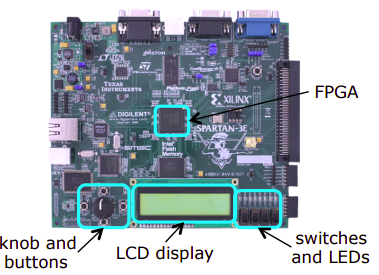
A special kind of integrated circuit called a Field Programmable Gate Array. First notice the LCD display at the bottom. This can be used to display two lines of 16 characters each. An FPGA is a circuit that can be “programmed” to monitor the behavior of other circuits. Since there are no significant costs for FPGA programming, new circuit testing with FPGAs provides an effective way to avoid costly errors later in the design process. In fact, some applications use FPGAs not only for prototyping but also in the final product.
What are the applications of digital circuits?
- Mobile Phones, Calculators and Digital Computers.
- Radios and communication Devices.
- Signal Generator.
- Smart Card.
- Cathode Ray Oscilloscope(CRO)
- Analog to digital converters (ADC)
- Digital to analog converters (DAC),
- Digital circuits are an integral part of all essential electronic equipment.
- Can be used to design your watch or timer.
- We use digital circuits in complex processes such as rocket science and quantum computing.
- Digital circuits are also used in traffic lights and automatic glass doors in offices and restaurants.
Also read here
- How to convert Jk flip-flop into D-flipflop?
- How to design a four bit adder-subtractor circuit?
- What are the Practical Aspects of Digital Circuit Design?
- What are the Transmission Gates?
- What are the Techniques for Testing Digital Circuits?
- What are the CMOS Logic Gates?
- What is the magnitude comparator circuit? Design a 3 bit magnitude comparator circuit
- What are the synchronous counters? Explain with an example.
- what are the half adder and full adder circuits?
- what are the half subtractor and full subtractor circuits?
- How to design a four bit adder-subtractor circuit?
- What are number systems in computer?
- Discuss the binary counter with parallel load? Explain its working with an example
- how to draw state diagram of sequential circuit?
- How to simplify a Boolean function using Karnaugh map (k-map)?
- What are the flip flops and registers in digital design?
- Define fan-in, fan-out, CMOS and TTL logic levels
- what is the Canonical form representation of Boolean function?
- What is difference between latches and flip flops?